A large majority of the problems associated with the Motorola and Delta units are due to low voltage battery input or grounding.
LOW VOLTAGE SYMPTOMS ARE WEAK SPARK OR SELECTIVE FIRING (WEAKLY) OF INDIVIDUAL CYLINDERS.
Basically, this test removes any grounding or contact point problems from the equation.
The test can be done on the Trackster
or at the workbench. Either way you must disconnect the CD amp wires from
the terminal bar on the
engine firewall. Refer to the
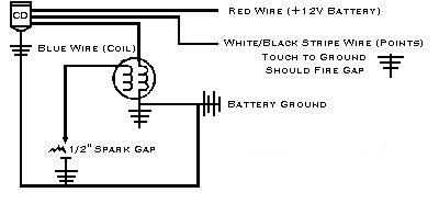
diagram (below) as needed.
1) The gray wire is unused.
2) The purple (red or pink after
20 years) wire attaches to the positive (+) side of the battery or any
12 volt DC power supply.
3) The blue wire connects to one
or both coils at the blue wire. The black wire and the body of the coil
connects to the negative(-) side (ground)
of the battery or 12 volt DC power
supply.
4) The black (or black with a
white stripe) wire with the spade connector which was attached to the engine
itself is the SWITCH. For the
moment, keep it away from everything
else.
5) Attach the body (any shiny
metal surface) of the CD amplifier also to the negative(-) side (ground)
of the battery or 12 volt DC power
supply.
6) Place a large nail or other
conductive rod sticking out of the spark plug wire from the coil (where
the spark plug normally goes)and arrange it
so the tip of the nail is about
1/2 inch from any of the grounded (negative) surfaces mentioned above.
This is the "spark gap".
7) Time to test. Tap the metal
connector attached to the black wire from step 4 to any of the grounded
(negative) surfaces mentioned above and
watch the air gap between the
nail and ground. You should see a nice blue spark. Oh yah! no explosives
near by. Right?
If you don't get a spark, the amplifier
is shot. Don't feel bad. It is by far the highest mortality part in a Trackster.
The main reasons for failure is
jumper cable starts, hooking up
a battery charger without removing the negative battery terminal or old,
cracked wires somewhere that cause a
short.